


Choice SNAF SERIES
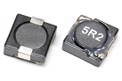
Low Profile, High Current Inductor
(SNAF73 series)
- FEATURES
-
‧Shielded construction.
‧Frequency range up to 5.0MHz.
‧Lowest DCR/µH, in this package size.
‧Handles high transient current spikes without saturation.
‧Ultra low buzz noise, due to composite construction.
‧100% Lead (Pb)-free and RoHS compliance. - APPLICATIONS
-
‧PDA/Notebook/Desktop/Server applications.
‧High current POL converters.
‧Low profile, high current power supplies.
‧Battery powered devices.
‧DC/DC converters in distributed power systems.
‧DC/DC converter for Field Programmable Gate Array (FPGA). - SHAPES & DIMENSIONS
-
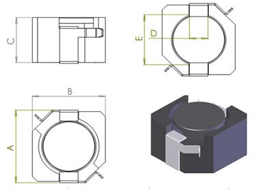
TYPE A B C D E SNAF73 8.0MAX 7.3±0.3 4.3MAX 1.8 TYP 4.4TYP - PRODUCT IDENTIFICATION
-
SNAF
 T -
-H
T -
-H 


 Product symbol
Dimensions
Taping
Inductance
Tolerance
HSF NOTES:
Suntechnic will start to release all Series inductors with lead-free terminals which meet SONY SS-00259's Scriteria for lead-free product in Q2 of 2004. - ELECTRICAL CHARACTERISTICS & NOTE
-
NOTES:PART NO. INDUCTANCE (µH) TOLERANCE (±%) DC RESISTANCE (mΩ) Irms (A) MAX Isat (A) MAX SNAF73T-R33N-H 0.33 30 7.3 6.21 14.4 SNAF73T-1R0N-H 1.0 30 10.2 5.28 7.79 SNAF73T-1R5M-H 1.5 20 13 4.67 6.52 SNAF73T-2R2M-H 2.2 20 15 4.15 5.52 SNAF73T-3R3M-H 3.3 20 16.5 3.31 4.22 SNAF73T-4R7M-H 4.7 20 25.9 3.09 3.78 SNAF73T-6R8M-H 6.8 20 43.5 2.55 3.12 SNAF73T-8R2M-H 8.2 20 59.2 2.19 2.66 SNAF73T-100M-H 10 20 65.5 2.08 2.47 SNAF73T-150M-H 15 20 84.4 1.83 2.05 SNAF73T-220M-H 22 20 107 1.02 1.67 SNAF73T-330M-H 33 20 166 1.31 1.35 SNAF73T-470M-H 47 20 241 1.08 1.14 SNAF73T-680M-H 68 20 358 0.89 0.96 SNAF73T-820M-H 82 20 384 0.86 0.89 SNAF73T-101M-H 100 20 527 0.73 0.79
1.Test Frequency 100KHZ 0.25Vrms.
2.All test data is referenced to 25°C ambient.
3.Operating Temperature Range - 55°C to + 105°C
4.DC current (A) that will cause an approximate ΔT of 40°C.
5.Sat current (A) that will cause Lo to drop approximately 30%
6.The part temperature (ambient + temp rise) should not exceed 125°C under worst case operating conditions. Circuit design, component placement, PWB trace size and thickness, airflow and other cooling provisions all affect the part temperature. Part temperature should be verified in the end application.
